课程 2 - 绘制圆
在这节课中你将学习到以下内容:
- 向画布中添加图形
- 使用 SDF 绘制一个圆形
- 反走样
- 脏检查模式
启动项目后将看到画布中绘制了一个圆,可以修改宽高或者切换 WebGL / WebGPU 渲染器。
width = Inputs.range([50, 300], { label: 'width', value: 100, step: 1 });height = Inputs.range([50, 300], { label: 'height', value: 100, step: 1 });renderer = Inputs.select(['webgl', 'webgpu'], { label: 'renderer' });canvas = (async () => {
const { Canvas, Circle } = Lesson2;
const canvas = await Utils.createCanvas(Canvas, 100, 100, renderer);
const circle = new Circle({
cx: 100,
cy: 100,
r: 100,
fill: 'red',
antiAliasingType: 3,
});
canvas.appendChild(circle);
let id;
const animate = () => {
canvas.render();
id = requestAnimationFrame(animate);
};
animate();
unsubscribe(() => {
cancelAnimationFrame(id);
canvas.destroy();
});
return canvas;
})();call(() => {
Utils.resizeCanvas(canvas, width, height);
});call(() => {
return canvas.getDOM();
});向画布中添加图形
上一课我们创建了一个空白画布,后续我们会向其中添加各种图形,如何设计这样的 API 呢?作为前端开发者,不妨借鉴熟悉的 Node API appendChild:
canvas.appendChild(shape);
canvas.removeChild(shape);
暂时创建一个图形基类,后续 Circle、Ellipse、Rect 等图形都会继承它:
export abstract class Shape {}在画布中使用数组存储图形列表:
#shapes: Shape[] = [];

appendChild(shape: Shape) {
  this.#shapes.push(shape);
}

removeChild(shape: Shape) {
  const index = this.#shapes.indexOf(shape);
  if (index !== -1) {
    this.#shapes.splice(index, 1);
  }
}
在画布渲染方法中遍历图形列表,调用渲染钩子:
render() {
  const { hooks } = this.#pluginContext;
  hooks.beginFrame.call();
  this.#shapes.forEach((shape) => {
    hooks.render.call(shape);
  });
  hooks.endFrame.call();
}
在渲染插件中每一帧开始前都会创建一个 RenderPass,硬件抽象层在这里进行了封装。WebGL 中并没有这个概念,WebGPU 中 beginRenderPass 会返回 GPURenderPassEncoder,通过它可以记录包括 draw 在内的一系列命令,后续在 render 钩子中我们会看到。在创建 RenderPass 时我们提供了以下参数:
colorAttachmentcolorResolveTo输出到屏幕colorClearColorWebGL 中通过 gl.clearColor 命令实现;WebGPU 中以 clearValue 属性声明,这里我们设置为白色。
hooks.beginFrame.tap(() => {
  this.#device.beginFrame();

  this.#renderPass = this.#device.createRenderPass({
    colorAttachment: [renderTarget],
    colorResolveTo: [onscreenTexture],
    colorClearColor: [TransparentWhite],
  });
});
与创建对应,在每一帧结束后提交 RenderPass,同样在 WebGPU 中很容易找到对应的 submit 方法,当然原生 API 提交的是一个编码后的命令缓冲,硬件抽象层简化了这些概念。
hooks.endFrame.tap(() => {
  this.#device.submitPass(this.#renderPass);
  this.#device.endFrame();
});
最后来到 render 钩子,每个图形负责实现绘制自身的逻辑,插件负责传入所需的 GPU 对象例如 Device 和 RenderPass。
hooks.render.tap((shape) => {
    // 稍后实现绘制逻辑
});
绘制圆形
首先我们需要定义圆形的基础属性,熟悉 SVG circle 的开发者一定知道,基于圆心 cx/cy 和半径 r 可以定义圆的几何形状,配合填充色 fill、描边色 stroke 这些通用绘图属性就能满足基础需求了。
export class Circle extends Shape {
    constructor(
        config: Partial<{
            cx: number;
            cy: number;
            r: number;
            fill: string;
        }> = {},
    ) {}
}
画布坐标系
既然提到 cx/cy 圆心这样的位置属性,就必须要明确我们使用的画布坐标系。在 Canvas 和 SVG 中,坐标系原点都是左上角,X 轴正向 👉,Y 轴正向 👇。但 WebGL 中使用的 [裁剪坐标系] 遵循 OpenGL 规范,原点在视口中心,X 轴正向 👉,Y 轴正向 👆,Z 轴正向向屏幕内。下面这个长宽高各为 2 的立方体也称作 normalized device coordinates (NDC):
但 WebGPU 遵循 Metal 规范,和 WebGL 有些差别,Y 轴正向 👇,Z 轴正向向外。另外在 Z 轴的裁剪范围上也有不同,WebGL 下为 [-1, 1],而 WebGPU 为 [0, 1]:
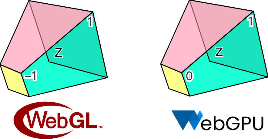
我们的硬件抽象层会尝试抹平 WebGL 和 WebGPU 的差异,但在坐标系上选择和 Canvas / SVG 保持一致,我们相信这更符合画板使用者的习惯。

因此如果我们的画布宽高均为 200,用如下方式添加的 Circle 将会出现在画布中心:
const circle = new Circle({
    cx: 100,
    cy: 100,
    r: 50,
    fill: 'red',
});
canvas.appendChild(circle);
下面的问题是如何将屏幕坐标系中的 cx/cy 转换成 NDC 交给渲染管线。后续我们会将画布的宽高以 Uniform 形式传入,圆的位置以 Attribute 传入,位置除以宽高将得到一个 [0, 1] 范围的值,乘以二再减一就可以转换成 [-1, 1] 即 NDC 下的范围值。最后翻转下 Y 轴:
layout(std140) uniform SceneUniforms {
  vec2 u_Resolution; // 画布宽高
};
layout(location = 1) in vec2 a_Position; // 圆心

// Pixel space to [0, 1] (Screen space)
vec2 zeroToOne = (a_Position + a_Size * a_FragCoord) / u_Resolution;

// Convert from [0, 1] to [0, 2]
vec2 zeroToTwo = zeroToOne * 2.0;

// Convert from [0, 2] to [-1, 1] (NDC/clip space)
vec2 clipSpace = zeroToTwo - 1.0;

// Flip Y axis
gl_Position = vec4(clipSpace * vec2(1, -1), 0.0, 1.0);
处理颜色值
不同于 Canvas 或者 SVG,字符串形式的颜色值是无法直接在 WebGL 或者 WebGPU 中使用的,好在 d3-color 可以帮助我们转换成 { r, g, b, opacity } 格式,后续可以直接以 vec4 或压缩形式传入 attribute 中。最后,我们暂时只支持 RGB 空间的颜色值,这意味着 hsl 等形式暂不可用:
import * as d3 from 'd3-color';

set fill(fill: string) {
  this.#fill = fill;
  this.#fillRGB = d3.rgb(fill); // { r, g, b, opacity }
}
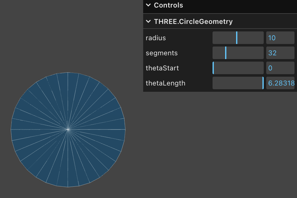
解决了样式问题,让我们回到几何部分。在三维渲染中三角网格(Triangle Mesh)是常用的几何表达,Three.js 中的 CircleGeometry 正是通过程序化生成几何的方式,将圆形从圆心出发分割成多个三角形。显然三角形越多圆就越平滑,如果只有两个三角形就退化成了正方形。为了得到一个平滑的圆,就需要较多的顶点,当圆的数目上升时会造成 GPU 内存显著增长。
SDF
使用一种名为 Signed Distance Functions(SDF)的方法只需要四个顶点。下图直观地展示了 SDF 的概念,来自新兴编辑器 Zed 的实践文章 drawing-rectangles。平面上的点之于一个半径为 100 的圆,在圆上距离为 0,在圆内和圆外分别为负值和正值:
原文中使用 Lottie 动画展示了有向距离场的定义和一些基础图形的公式推导过程。在 Zed 的 GPUI 中也使用 SDF 绘制基础图形以获取更好的性能。
通常我们在 Vertex Shader 中构建坐标系:
layout(location = 0) in vec2 a_FragCoord;
out vec2 v_FragCoord;
void main() {
  v_FragCoord = a_FragCoord;
}
有了距离信息就可以在 Fragment Shader 中依据不同图形的 SDF 公式,将当前像素点坐标带入就可以判断点是否在图形内部,如果在外部就可以直接丢弃,否则进行着色,GLSL 代码如下:
float sdf_circle(vec2 p, float r) {
  return length(p) - r;
}

void main() {
  float distance = sdf_circle(v_FragCoord, 1.0);
  if (distance > 0.0) { // 在圆外,直接丢弃
    discard;
  }
  outputColor = vec4(1.0, 0.0, 0.0, 1.0); // 着色
}
除了更少的顶点使用,SDF 还具有以下优点:
- 易于抗锯齿/反走样。我们在下一小节会介绍它。
- 易于组合。交集、差集运算可以通过组合完成复杂图形的绘制。
- 易于实现一些看起来很复杂的效果。例如描边、圆角、阴影,当然我们后续在实现这些效果时也会介绍该方法的一些局限性。
对于 SDF 的解释和详细推导过程也可以在 distfunctions 中找到,这种方法可以绘制各种常见的 2D 甚至是 3D 图形,后续我们也会继续使用该方法绘制矩形和文本。
让我们回到图形基类,我们增加一个方法接收所需参数进行绘制:
export abstract class Shape {
  abstract render(device: Device, renderPass: RenderPass): void;
}
在插件的 render 钩子中调用并传入所需参数:
hooks.render.tap((shape) => {
    shape.render(this.#device, this.#renderPass);
});
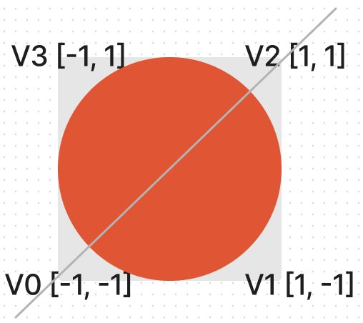
在 Circle 的 render 方法中构建一个单位坐标系,和 clip space 一致,包含四个顶点,通过 indexBuffer 索引数组分割成两个三角形(V0 -> V1 -> V2 和 V0 -> V2 -> V3):
this.#fragUnitBuffer = device.createBuffer({
    viewOrSize: new Float32Array([-1, -1, 1, -1, 1, 1, -1, 1]),
    usage: BufferUsage.VERTEX,
});

this.#indexBuffer = device.createBuffer({
    viewOrSize: new Uint32Array([0, 1, 2, 0, 2, 3]),
    usage: BufferUsage.INDEX,
});
在这四个顶点中,每个顶点可以共享同样的样式属性,例如圆心、半径、填充色等。这样可以减少顶点数组内存的大小:
this.#instancedBuffer = device.createBuffer({
    viewOrSize: new Float32Array([
        this.#cx,
        this.#cy,
        this.#r,
        this.#r,
        this.#fillRGB.r / 255,
        this.#fillRGB.g / 255,
        this.#fillRGB.b / 255,
        this.#fillRGB.opacity,
    ]),
    usage: BufferUsage.VERTEX,
});
接着指定顶点数组的排布方式,通过 shaderLocation 和 Shader 关联
this.#inputLayout = device.createInputLayout({
    vertexBufferDescriptors: [
        {
            arrayStride: 4 * 2,
            stepMode: VertexStepMode.VERTEX,
            attributes: [
                {
                    shaderLocation: 0, // layout(location = 0) in vec2 a_FragCoord;
                    offset: 0,
                    format: Format.F32_RG,
                },
            ],
        },
        {
            arrayStride: 4 * 8,
            stepMode: VertexStepMode.INSTANCE,
            attributes: [
                {
                    shaderLocation: 1, // layout(location = 1) in vec2 a_Position;
                    offset: 0,
                    format: Format.F32_RG,
                },
                {
                    shaderLocation: 2, // layout(location = 2) in vec2 a_Size;
                    offset: 4 * 2,
                    format: Format.F32_RG,
                },
                {
                    shaderLocation: 3, // layout(location = 3) in vec4 a_FillColor;
                    offset: 4 * 4,
                    format: Format.F32_RGBA,
                },
            ],
        },
    ],
    indexBufferFormat: Format.U32_R,
    program: this.#program,
});
SDF 还可以用来绘制椭圆、矩形、文本等等,但我们暂时不打算继续添加其他图形,先来关注另一个问题。
反走样
仔细观察或者放大可以看到边缘明显的锯齿,毕竟在 Fragment Shader 中我们对于每个像素点使用了粗暴的判定方式:要么着色要么丢弃,完全没有过渡的中间地带。
(async () => {
    const { Canvas, Circle } = Lesson2;

    const canvas = await Utils.createCanvas(Canvas, 200, 200);

    const circle = new Circle({
        cx: 100,
        cy: 100,
        r: 100,
        fill: 'red',
    });
    canvas.appendChild(circle);

    const animate = () => {
        canvas.render();
        requestAnimationFrame(animate);
    };
    animate();
    return canvas.getDOM();
})();
下面我们参考 Smooth SDF Shape Edges 一文,使用几种不同方式并对比效果。
Smoothstep
首先我们想到可以通过 GLSL / WGSL 的内置函数 smoothstep 进行平滑处理,相比 step 函数它可以为一个指定范围的值生成平滑后的对应值,类似缓动函数 ease-in/out 的效果。你可以在 Smoothstep - thebookofshaders.com 中修改参数直观看到它的形状,例如下图中 x 大于 0 时 y 为 1;x 小于 -0.5 时 y 为 0;中间的区域平滑过渡:
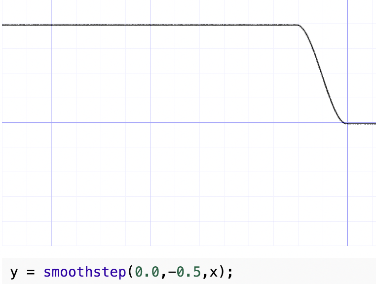
上一节计算出的 SDF 距离是一个负值,我们选取一个固定的较小值 0.01,这样边缘处较小的距离范围可以得到平滑处理,处理后的值可以当作透明度。
float alpha = smoothstep(0.0, 0.01, -distance);

outputColor = v_FillColor;
outputColor.a *= alpha;
效果如下:
(async () => {
    const { Canvas, Circle } = Lesson2;

    const canvas = await Utils.createCanvas(Canvas, 200, 200);

    const circle = new Circle({
        cx: 100,
        cy: 100,
        r: 100,
        fill: 'red',
        antiAliasingType: 1,
    });
    canvas.appendChild(circle);

    const animate = () => {
        canvas.render();
        requestAnimationFrame(animate);
    };
    animate();
    return canvas.getDOM();
})();
这种方法的问题是会稍稍增大圆的半径,毕竟多出了百分之一。另外在放大时(稍后会介绍相机相关功能)边缘不够锐利。
Divide fixed
GLSL 中没有 saturate 函数,可以使用 clamp 实现:
float alpha = clamp(-distance / 0.01, 0.0, 1.0);(async () => {
const { Canvas, Circle } = Lesson2;
const canvas = await Utils.createCanvas(Canvas, 200, 200);
const circle = new Circle({
cx: 100,
cy: 100,
r: 100,
fill: 'red',
antiAliasingType: 2,
});
canvas.appendChild(circle);
const animate = () => {
canvas.render();
requestAnimationFrame(animate);
};
animate();
return canvas.getDOM();
})();fwidth
在 Using fwidth for distance based anti-aliasing 一文中介绍了使用 fwidth 对 SDF 进行反走样的方法。那什么是 fwidth 呢?
What are screen space derivatives and when would I use them? 和 What is fwidth and how does it work? 这个两个回答详细介绍了该方法的概念和计算方式。简而言之 Fragment shader 每次处理的是 2x2 的 quad 而非单一像素点。GPU 这么做的理由如下,来自 A trip through the Graphics Pipeline 2011, part 8
Also, this is a good point to explain why we’re dealing with quads of 2×2 pixels and not individual pixels. The big reason is derivatives. Texture samplers depend on screen-space derivatives of texture coordinates to do their mip-map selection and filtering (as we saw back in part 4); and, as of shader model 3.0 and later, the same machinery is directly available to pixel shaders in the form of derivative instructions.
下面来看在每个 2x2 quad 中偏导数是如何计算的,例如对于 uv:
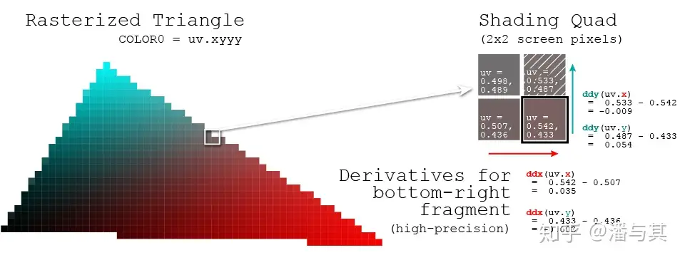
因此便于开发者获取该像素点针对某个值的变化剧烈程度,OpenGL / WebGL 和 WebGPU 都提供了以下方法:
dFdx计算屏幕水平方向上,一像素跨度内参数属性值改变了多少dFdy计算屏幕垂直方向上,一像素跨度内参数属性值改变了多少fwidth计算abs(dFdx) + abs(dFdy)
我们把 SDF 计算得到的距离传入,计算得到它的变化程度最终反映在透明度上。
float alpha = clamp(-distance / fwidth(-distance), 0.0, 1.0);(async () => {
const { Canvas, Circle } = Lesson2;
const canvas = await Utils.createCanvas(Canvas, 200, 200);
const circle = new Circle({
cx: 100,
cy: 100,
r: 100,
fill: 'red',
antiAliasingType: 3,
});
canvas.appendChild(circle);
const animate = () => {
canvas.render();
requestAnimationFrame(animate);
};
animate();
return canvas.getDOM();
})();脏检查
之前我们把填充色、圆心等样式属性都写入了顶点数组中,因此当我们想修改颜色时,也需要重新修改 Buffer 中的数据。对于下面例子中的连续修改场景,如果每次修改属性都立即调用底层 API,将造成大量不必要的开销。
circle.fill = 'blue';
circle.fill = 'yellow';
circle.cx = 500;我们想推迟修改数据这样的耗时任务,在合适的时机例如渲染前合并处理,此时可以应用“脏检查”这种常见的设计模式:Dirty Flag - Game Programming Patterns。在修改属性时我们仅仅设置脏检查标记,并不执行其他耗时操作:
set cx(cx: number) {
  if (this.#cx !== cx) {
    this.#cx = cx;
    this.renderDirtyFlag = true;
  }
}
在 render 方法中,检测到属性确实发生了修改时才更新底层 Buffer,这样两次渲染间隔内,无论发生多少次属性修改,也都只会更新 Buffer 一次:
if (this.renderDirtyFlag) {
    this.#instancedBuffer.setSubData(
        0,
        new Uint8Array(
            new Float32Array([
                this.#cx,
                this.#cy,
                this.#r,
                this.#r,
                this.#fillRGB.r / 255,
                this.#fillRGB.g / 255,
                this.#fillRGB.b / 255,
                this.#fillRGB.opacity,
            ]).buffer,
        ),
    );
}
当然,渲染完成后别忘了重置脏检查标记:
this.renderDirtyFlag = false;试试效果:
cx2 = Inputs.range([50, 300], { label: 'cx', value: 100, step: 1 });cy2 = Inputs.range([50, 300], { label: 'cy', value: 100, step: 1 });r2 = Inputs.range([50, 300], { label: 'r', value: 100, step: 1 });fill2 = Inputs.color({ label: 'fill', value: '#ff0000' });circle = (() => {
const { Circle } = Lesson2;
const circle = new Circle({
cx: 100,
cy: 100,
r: 100,
fill: 'red',
antiAliasingType: 3,
});
return circle;
})();(() => {
circle.cx = cx2;
circle.cy = cy2;
circle.r = r2;
circle.fill = fill2;
})();(async () => {
const { Canvas } = Lesson2;
const canvas = await Utils.createCanvas(Canvas, 200, 200);
canvas.appendChild(circle);
let id;
const animate = () => {
canvas.render();
id = requestAnimationFrame(animate);
};
animate();
unsubscribe(() => {
cancelAnimationFrame(id);
canvas.destroy();
});
return canvas.getDOM();
})();在后续介绍到场景图时,我们还将应用脏检查模式。