Lesson 2 - Draw a circle
In this lesson you will learn the following:
- Adding shapes to the canvas
- Drawing a circle using SDF
- Anti Aliasing
- Dirty flag design pattern
When you start the project you will see a circle drawn in the canvas and you can modify the width and height or switch the WebGL / WebGPU renderer.
width = Inputs.range([50, 300], { label: 'width', value: 100, step: 1 });height = Inputs.range([50, 300], { label: 'height', value: 100, step: 1 });renderer = Inputs.select(['webgl', 'webgpu'], { label: 'renderer' });canvas = (async () => {
const { Canvas, Circle } = Lesson2;
const canvas = await Utils.createCanvas(Canvas, 100, 100, renderer);
const circle = new Circle({
cx: 100,
cy: 100,
r: 100,
fill: 'red',
antiAliasingType: 3,
});
canvas.appendChild(circle);
let id;
const animate = () => {
canvas.render();
id = requestAnimationFrame(animate);
};
animate();
unsubscribe(() => {
cancelAnimationFrame(id);
canvas.destroy();
});
return canvas;
})();call(() => {
Utils.resizeCanvas(canvas, width, height);
});call(() => {
return canvas.getDOM();
});Adding shapes to canvas
In the last lesson we created a blank canvas to which we will subsequently add various graphics, how to design such an API? As a front-end developer, you may want to draw on the familiar Node API appendChild:
canvas.appendChild(shape);
canvas.removeChild(shape);
Temporarily create a graphic base class, which will be inherited by Circle, Ellipse, Rect and so on:
export abstract class Shape {}Use an array to store a list of shapes in the canvas:
#shapes: Shape[] = [];

appendChild(shape: Shape) {
  this.#shapes.push(shape);
}

removeChild(shape: Shape) {
  const index = this.#shapes.indexOf(shape);
  if (index !== -1) {
    this.#shapes.splice(index, 1);
  }
}
Iterate through the list of shapes in the canvas render method and call the render hook:
render() {
  const { hooks } = this.#pluginContext;
  hooks.beginFrame.call();
  this.#shapes.forEach((shape) => {
    hooks.render.call(shape);
  });
  hooks.endFrame.call();
}
In the render plugin a RenderPass is created before the start of each frame, which is encapsulated in the hardware abstraction layer. there is no such concept in WebGL, but in WebGPU beginRenderPass returns GPURenderPassEncoder, which records a series of commands, including draw, as we will see later in the render hook. commands, as we'll see later in the render hook. When creating RenderPass we provide the following parameters:
colorAttachmentcolorResolveTocolorClearColorThis is implemented in WebGL with the gl.clearColor command; in WebGPU it is declared with the clearValue property, which we set to white here.
hooks.beginFrame.tap(() => {
  this.#device.beginFrame();

  this.#renderPass = this.#device.createRenderPass({
    colorAttachment: [renderTarget],
    colorResolveTo: [onscreenTexture],
    colorClearColor: [TransparentWhite],
  });
});
Corresponding to creation, submitting RenderPass at the end of each frame, again the corresponding submit method is easy to find in the WebGPU, but of course the native API submits a coded command buffer, and the hardware abstraction layer simplifies these concepts.
hooks.endFrame.tap(() => {
  this.#device.submitPass(this.#renderPass);
  this.#device.endFrame();
});
Finally, we come to the render hook, where each graph is responsible for implementing the logic to draw itself, and the plugin is responsible for passing in the required GPU objects such as Device and RenderPass.
hooks.render.tap((shape) => {});Draw a circle
The first thing we need to do is to define the basic attributes of a circle. Those of you who are familiar with SVG circle will know that you can define the geometry of a circle based on its center, cx/cy, and its radius, r, and that you can use the generic drawing attributes of fill and stroke to satisfy the basic needs.
export class Circle extends Shape {
    constructor(
        config: Partial<{
            cx: number;
            cy: number;
            r: number;
            fill: string;
        }> = {},
    ) {}
}
Canvas coordinates
Since we're talking about positional attributes like the center of the cx/cy circle, it's important to be clear about the canvas coordinate system we're using. In both Canvas and SVG, the origin of the coordinate system is the upper-left corner, X-axis positive 👉, Y-axis positive 👇. However, the [cropping coordinate system] used in WebGL follows the OpenGL specification, with the origin at the center of the viewport, the X-axis pointing 👉, the Y-axis pointing 👆, and the Z-axis pointing inward toward the screen. The cube below, which has an aspect ratio of 2, is also known as normalized device coordinates (NDC):

However, WebGPU follows the Metal specification, which differs from WebGL in that the Y-axis is forward 👇 and the Z-axis is forward outward. There is also a difference in the cropping range of the Z-axis, which is [-1, 1] in WebGL and [0, 1] in WebGPU:
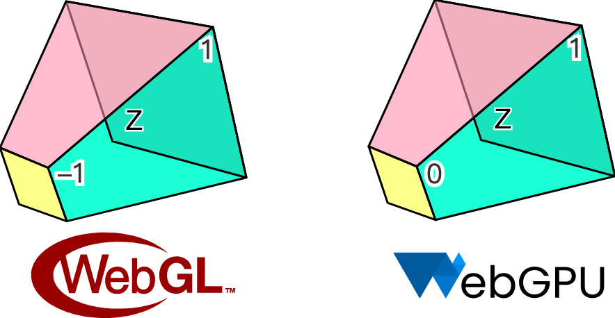
Our hardware abstraction layer tries to smooth out the differences between WebGL and WebGPU, but chooses to align with Canvas / SVG in terms of coordinate system, which we believe is more in line with what board users are used to.

So if our canvas has a width and height of 200, the Circle added in the following way will appear in the center of the canvas:
const circle = new Circle({
    cx: 100,
    cy: 100,
    r: 50,
    fill: 'red',
});
canvas.appendChild(circle);
The next question is how to convert cx/cy in the screen coordinate system into NDC for the render pipeline. We'll pass in the width and height of the canvas as a Uniform, and the position of the circle as an Attribute. Dividing the position by the width and height will give us a value in the range [0, 1], which is multiplied by two and subtracted by one to convert to [-1, 1], which is the range of values under NDC. Finally, flip down the Y-axis:
layout(std140) uniform SceneUniforms {
  vec2 u_Resolution; // width & height of canvas
};
layout(location = 1) in vec2 a_Position; // cx & cy

// Pixel space to [0, 1] (Screen space)
vec2 zeroToOne = (a_Position + a_Size * a_FragCoord) / u_Resolution;

// Convert from [0, 1] to [0, 2]
vec2 zeroToTwo = zeroToOne * 2.0;

// Convert from [0, 2] to [-1, 1] (NDC/clip space)
vec2 clipSpace = zeroToTwo - 1.0;

// Flip Y axis
gl_Position = vec4(clipSpace * vec2(1, -1), 0.0, 1.0);
Processing color values
Unlike Canvas or SVG, color values in string form can't be used directly in WebGL or WebGPU, but d3-color can be converted to { r, g, b, opacity } format, which can then be passed directly into attribute as vec4 or compressed. Finally, we only support RGB-space color values for now, which means that hsl and the like are not available:
import * as d3 from 'd3-color';
set fill(fill: string) {
this.#fill = fill;
this.#fillRGB = d3.rgb(fill); // { r, g, b, opacity }
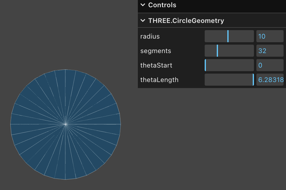
}With the style issue out of the way, let's get back to the geometry. Triangle Mesh is a common representation of geometry in 3D rendering, and CircleGeometry in Three.js procedurally generates the geometry by splitting the circle into triangles from the center. Obviously, the more triangles there are, the smoother the circle will be, and if there are only two triangles, it will degenerate into a square. In order to get a smooth circle, more vertices are needed, which causes a significant increase in GPU memory as the number of circles goes up.
SDF
Only four vertices are needed using a method called Signed Distance Functions (SDF). The following diagram visualizes the concept of SDFs, from the hands-on article drawing-rectangles by the emergent editor Zed. A point in the plane is a circle of radius 100 with a distance of 0 on the circle, and negative and positive values inside and outside the circle, respectively:

The original article uses Lottie animations to show the definition of a directed distance field and the derivation of some formulas for the underlying graph. In Zed's GPUI, SDF is also used to draw the underlying graphs for better performance.
Normally we build the coordinate system in the Vertex Shader.
layout(location = 0) in vec2 a_FragCoord;
out vec2 v_FragCoord;
void main() {
  v_FragCoord = a_FragCoord;
}
With the distance information, you can use the SDF formula of different graphics in the Fragment Shader to bring in the coordinates of the current pixel to determine whether the point is inside the graphic, if it is outside, it can be directly discarded, otherwise it will be colored, the GLSL code is as follows:
float sdf_circle(vec2 p, float r) {
  return length(p) - r;
}

void main() {
  float distance = sdf_circle(v_FragCoord, 1.0);
  if (distance > 0.0) {
    discard;
  }
  outputColor = vec4(1.0, 0.0, 0.0, 1.0);
}
In addition to using fewer vertices, SDF offers the following advantages:
- Easy anti-aliasing. We will cover it in the next subsection.
- Easy to combine. Intersection and difference operations can be combined to complete complex graphs.
- It is easy to realize some complex-looking effects. For example, strokes, rounded corners, shadows, of course, we will introduce some limitations of this method when we realize these effects.
An explanation and detailed derivation of the SDF can also be found in distfunctions. This method can be used to draw a variety of common 2D and even 3D shapes, and we'll continue to use it to draw rectangles and text.
Let's go back to the graphics base class and add a method that takes the required parameters to draw:
export abstract class Shape {
  abstract render(device: Device, renderPass: RenderPass): void;
}
Called in the plugin's render hook and passed in the required parameters:
hooks.render.tap((shape) => {
    shape.render(this.#device, this.#renderPass);
});
Constructs a unitary coordinate system in the render method of Circle, consistent with clip space, containing four vertices split into two triangles (V0 -> V1 -> V2 and V0 -> V2 -> V3) via the indexBuffer index array:
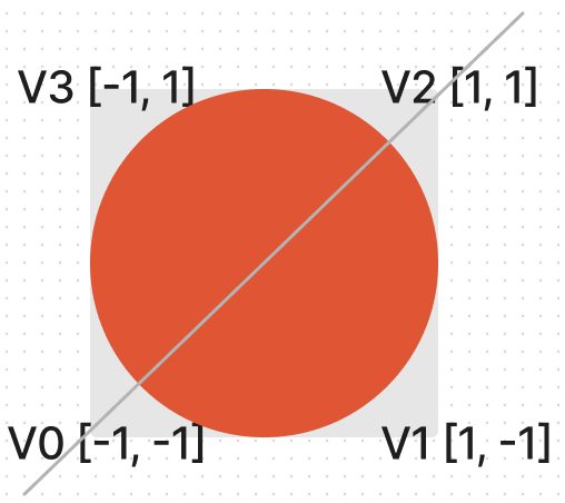
this.#fragUnitBuffer = device.createBuffer({
    viewOrSize: new Float32Array([-1, -1, 1, -1, 1, 1, -1, 1]),
    usage: BufferUsage.VERTEX,
});

this.#indexBuffer = device.createBuffer({
    viewOrSize: new Uint32Array([0, 1, 2, 0, 2, 3]),
    usage: BufferUsage.INDEX,
});
Each of these four vertices can share the same style attributes, such as circle center, radius, fill color, etc. This reduces the size of the vertex array memory:
this.#instancedBuffer = device.createBuffer({
    viewOrSize: new Float32Array([
        this.#cx,
        this.#cy,
        this.#r,
        this.#r,
        this.#fillRGB.r / 255,
        this.#fillRGB.g / 255,
        this.#fillRGB.b / 255,
        this.#fillRGB.opacity,
    ]),
    usage: BufferUsage.VERTEX,
});
Next, specify how the array of vertices should be laid out, which is associated with the shader via shaderLocation.
this.#inputLayout = device.createInputLayout({
    vertexBufferDescriptors: [
        {
            arrayStride: 4 * 2,
            stepMode: VertexStepMode.VERTEX,
            attributes: [
                {
                    shaderLocation: 0, // layout(location = 0) in vec2 a_FragCoord;
                    offset: 0,
                    format: Format.F32_RG,
                },
            ],
        },
        {
            arrayStride: 4 * 8,
            stepMode: VertexStepMode.INSTANCE,
            attributes: [
                {
                    shaderLocation: 1, // layout(location = 1) in vec2 a_Position;
                    offset: 0,
                    format: Format.F32_RG,
                },
                {
                    shaderLocation: 2, // layout(location = 2) in vec2 a_Size;
                    offset: 4 * 2,
                    format: Format.F32_RG,
                },
                {
                    shaderLocation: 3, // layout(location = 3) in vec4 a_FillColor;
                    offset: 4 * 4,
                    format: Format.F32_RGBA,
                },
            ],
        },
    ],
    indexBufferFormat: Format.U32_R,
    program: this.#program,
});
SDFs can also be used to draw ellipses, rectangles, text, and so on, but we're not going to go ahead and add other shapes for now, and focus on another issue first.
Antialiasing
If you look closely or zoom in, you can see that the edges are clearly jagged. After all, in the Fragment Shader we use a brute force decision for each pixel point: either color it or discard it, with no transition in between.
(async () => {
    const { Canvas, Circle } = Lesson2;

    const canvas = await Utils.createCanvas(Canvas, 200, 200);

    const circle = new Circle({
        cx: 100,
        cy: 100,
        r: 100,
        fill: 'red',
    });
    canvas.appendChild(circle);

    let id;
    const animate = () => {
        canvas.render();
        id = requestAnimationFrame(animate);
    };
    animate();

    unsubscribe(() => {
        cancelAnimationFrame(id);
        canvas.destroy();
    });
    return canvas.getDOM();
})();
Below we refer to the article Smooth SDF Shape Edges to use several different approaches and compare the results.
Smoothstep
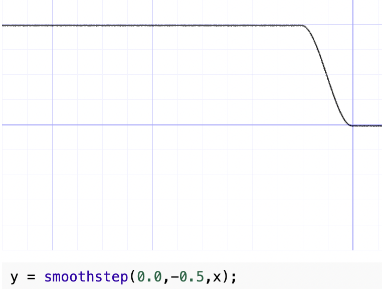
The first thing that comes to mind is that we can do smoothing with GLSL / WGSL's built-in function smoothstep, which generates a smoothed value for a specified range of values, similar to the effect of the easing function ease-in/out, compared to the step function. You can visualize its shape by modifying the parameters in Smoothstep - thebookofshaders.com, e.g. in the following figure, y is 1 when x is greater than 0, y is 0 when x is less than -0.5, and the area in between is smoothed:
The SDF distance calculated in the previous section is a negative value, and we pick a fixed smaller value of 0.01 so that the smaller range of distances at the edges can be smoothed, and the processed value can be treated as transparency.
float alpha = smoothstep(0.0, 0.01, -distance);

outputColor = v_FillColor;
outputColor.a *= alpha;
The effect is as follows:
(async () => {
    const { Canvas, Circle } = Lesson2;

    const canvas = await Utils.createCanvas(Canvas, 200, 200);

    const circle = new Circle({
        cx: 100,
        cy: 100,
        r: 100,
        fill: 'red',
        antiAliasingType: 1,
    });
    canvas.appendChild(circle);

    let id;
    const animate = () => {
        canvas.render();
        id = requestAnimationFrame(animate);
    };
    animate();

    unsubscribe(() => {
        cancelAnimationFrame(id);
        canvas.destroy();
    });
    return canvas.getDOM();
})();
The problem with this method is that it slightly increases the radius of the circle, after all it is one percent more. Also when zoomed in (more on camera related features later) the edges are not sharp enough.
Divide fixed
The saturate function is not available in GLSL and can be implemented using clamp:
float alpha = clamp(-distance / 0.01, 0.0, 1.0);(async () => {
const { Canvas, Circle } = Lesson2;
const canvas = await Utils.createCanvas(Canvas, 200, 200);
const circle = new Circle({
cx: 100,
cy: 100,
r: 100,
fill: 'red',
antiAliasingType: 2,
});
canvas.appendChild(circle);
let id;
const animate = () => {
canvas.render();
id = requestAnimationFrame(animate);
};
animate();
unsubscribe(() => {
cancelAnimationFrame(id);
canvas.destroy();
});
return canvas.getDOM();
})();fwidth
Using fwidth for distance based anti-aliasing is described in Using fwidth for distance based anti-aliasing. What is fwidth?
What are screen space derivatives and when would I use them? and What is fwidth and how does it work? describe the concepts and calculations of the method in detail. In a nutshell, the Fragment shader processes a 2x2 quad at a time instead of a single pixel point. the GPU's reasoning for doing this is as follows from the A trip through the Graphics Pipeline 2011, part 8:
Also, this is a good point to explain why we’re dealing with quads of 2×2 pixels and not individual pixels. The big reason is derivatives. Texture samplers depend on screen-space derivatives of texture coordinates to do their mip-map selection and filtering (as we saw back in part 4); and, as of shader model 3.0 and later, the same machinery is directly available to pixel shaders in the form of derivative instructions.
Here's a look at how the partial derivatives are calculated in each 2x2 quad, e.g. for uv:
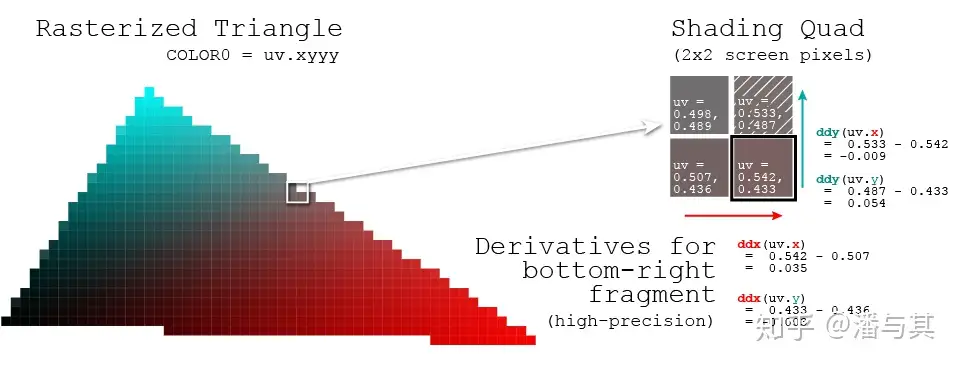
To make it easier for developers to get a sense of how drastically the pixel has changed for a given value, both OpenGL / WebGL and WebGPU provide the following methods:
dFdxCalculates how much the value of a parameter attribute has changed over the span of one pixel in the horizontal direction of the screen.dFdyCalculates how much the value of a parameter attribute has changed over a one-pixel span in the vertical direction of the screen.fwidthcalculates `abs(dFdx) + abs(dFdy)
We pass in the distance from the SDF calculation and calculate how much it has changed to be reflected in the transparency.
float alpha = clamp(-distance / fwidth(-distance), 0.0, 1.0);(async () => {
const { Canvas, Circle } = Lesson2;
const canvas = await Utils.createCanvas(Canvas, 200, 200);
const circle = new Circle({
cx: 100,
cy: 100,
r: 100,
fill: 'red',
antiAliasingType: 3,
});
canvas.appendChild(circle);
let id;
const animate = () => {
canvas.render();
id = requestAnimationFrame(animate);
};
animate();
unsubscribe(() => {
cancelAnimationFrame(id);
canvas.destroy();
});
return canvas.getDOM();
})();Dirty flag
Previously, we wrote the style attributes such as fill color and center of circle into the vertex array, so when we want to modify the color, we also need to re-modify the data in the Buffer. For the continuous modification scenario in the example below, it would cause a lot of unnecessary overhead if the underlying API is called immediately every time a property is modified.
circle.fill = 'blue';
circle.fill = 'yellow';
circle.cx = 500;
We want to postpone time-consuming tasks such as modifying data and merge them at the right time, e.g. before rendering, by applying a common design pattern called "dirty flag": [Dirty Flag - Game Programming Patterns]. When modifying a property, we simply set a dirty flag and do not perform any other time-consuming operations:
set cx(cx: number) {
  if (this.#cx !== cx) {
    this.#cx = cx;
    this.renderDirtyFlag = true;
  }
}
In the render method, the underlying buffer is updated only when a property modification is detected, so that no matter how many times a property modification occurs between renders, the buffer is only updated once:
if (this.renderDirtyFlag) {
    this.#instancedBuffer.setSubData(
        0,
        new Uint8Array(
            new Float32Array([
                this.#cx,
                this.#cy,
                this.#r,
                this.#r,
                this.#fillRGB.r / 255,
                this.#fillRGB.g / 255,
                this.#fillRGB.b / 255,
                this.#fillRGB.opacity,
            ]).buffer,
        ),
    );
}
Of course, don't forget to reset the dirty flag when the rendering is done:
this.renderDirtyFlag = false;Try the effect:
cx2 = Inputs.range([50, 300], { label: 'cx', value: 100, step: 1 });cy2 = Inputs.range([50, 300], { label: 'cy', value: 100, step: 1 });r2 = Inputs.range([50, 300], { label: 'r', value: 100, step: 1 });fill2 = Inputs.color({ label: 'fill', value: '#ff0000' });circle = (() => {
const { Circle } = Lesson2;
const circle = new Circle({
cx: 100,
cy: 100,
r: 100,
fill: 'red',
antiAliasingType: 3,
});
return circle;
})();(() => {
circle.cx = cx2;
circle.cy = cy2;
circle.r = r2;
circle.fill = fill2;
})();(async () => {
const { Canvas } = Lesson2;
const canvas = await Utils.createCanvas(Canvas, 200, 200);
canvas.appendChild(circle);
let id;
const animate = () => {
canvas.render();
id = requestAnimationFrame(animate);
};
animate();
unsubscribe(() => {
cancelAnimationFrame(id);
canvas.destroy();
});
return canvas.getDOM();
})();In the subsequent introduction to scene graphs, we will also apply the dirty flag.